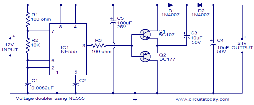
A 555 timer IC is probably one of the most used IC in electronics. Here is a simple diagram of voltage doubler using the 555 timer IC.

Components needed:
You can figure out the components needed from the circuit diagram itself.
Note:
You can use many of the other variations of the 555 timer IC. As in here it is NE555, but you can use LM555 or any other variation.
Working:
The 555 IC is in astable multivibrator mode.
First Half: When the output of our multivibrator is low, Q1 (because it is NPN transistor) will be OFF and Q2 (because it is PNP transistor) will be ON. So the negative terminal of capacitor C3 will be connected to ground. It will charge from the power supply and through the D1 diode.
Second Half: When the o/p of multivibrator is High, Q1 will be ON and Q2 will be OFF. . The C4 capacitor will be charged by the voltage of C3 capacitor. But its discharge through transistor Q1 is blocked by D1 diode. Discharge of C4 through Q1 during next half (that is low voltage of the multivibrator) is blocked by D2 diode.
Now, What will be the total o/p????
It will be sum of C4 voltage and the supply voltage. So it will be nearly doubled.
Note:
1. The o/p will be nearly 18v for 12v supply.
2. These are specifications for a frequency of 9KHz. But it can be varied by varying the values of R1 and C1.
3. The o/p current will be max of 50mA. So observe the voltage and calculate the current the load resistance according to that.
Hope you will find it interesting and helping....
Leave your response and requests in the comment section below....
Thanks for visiting...
Follow the blog if you like my efforts... :)
No comments:
Post a Comment